
Detailed Explanation of Circuit Knowledge for New Energy Charging Systems
The Coordination Mechanism between SECC and EVCC
Amid the rapid development of new energy vehicles, the charging system serves as a crucial link connecting the power grid and vehicles. Its circuit design and protocol interaction directly impact charging efficiency, safety, and compatibility. Among its components, the SECC (Supply Equipment Communication Controller) and EVCC (Electric Vehicle Communication Controller) are the core parts of the charging system, forming the “neural center” of the entire charging process. This article will conduct an in-depth analysis of the core technologies of new energy charging systems from dimensions such as circuit composition, protocol interaction, and safety mechanisms.
I. Basic Architecture of the Charging System
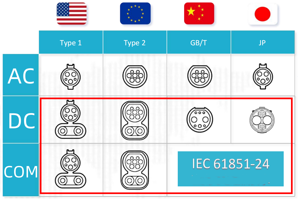
The new energy vehicle charging system mainly consists of two parts: the charging equipment (such as a charging pile, referred to as the “pile side” for short) belonging to the SECC, and the on-board charging system (referred to as the “vehicle side” for short) belonging to the EVCC. These two parts achieve physical connection through the charging plug and socket, and complete data interaction and energy transmission via standardized protocols.
In terms of functional division, the SECC is responsible for energy conversion, load management, and safety monitoring on the power grid side, while the EVCC undertakes energy reception, battery status monitoring, and charging demand feedback on the vehicle side. The collaborative work of the two can be divided into three stages: physical connection confirmation, protocol handshake and parameter configuration, and energy transmission and status monitoring.
1. Circuit Composition and Functional Implementation of SECC
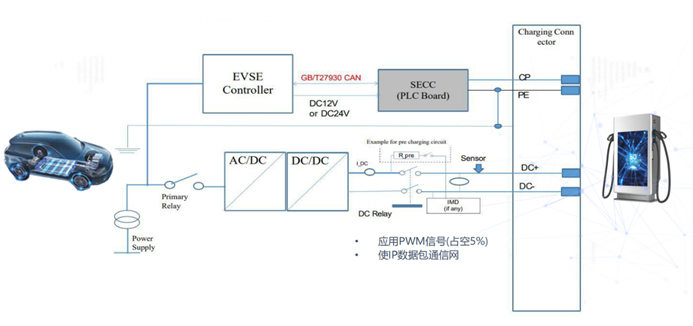
As the control core of the charging pile, the circuit system of the SECC (Supply Equipment Communication Controller) can be divided into three major parts: the power conversion module, the control and communication module, and the safety protection module.
The power conversion module serves as the “main artery” for energy transmission, mainly consisting of a rectifier circuit, a Power Factor Correction (PFC) circuit, and a DC/AC conversion circuit. In AC charging piles, the 220V or 380V utility-frequency AC power is converted into DC power via a rectifier bridge, and then the PFC circuit optimizes the input power factor to reduce harmonic pollution. DC charging piles, on the other hand, add a DC/DC conversion circuit on this basis to convert high-voltage DC power into a voltage level that meets the vehicle’s requirements. Taking a common 60kW DC charging pile as an example, its power module typically uses IGBTs (Insulated Gate Bipolar Transistors) as switching devices, and achieves precise voltage and current control through high-frequency Pulse Width Modulation (PWM).
The control and communication module is the “brain” of the SECC. With an STM32 or DSP chip as the core MCU (Microcontroller Unit), it integrates interface circuits such as CAN bus, Ethernet, and wireless communication (4G/5G). Among them, the CAN communication circuit is responsible for underlying data interaction with the EVCC (Electric Vehicle Communication Controller), complying with the ISO 11898 standard; the Ethernet interface is used for communication with the charging pile management platform to realize remote monitoring and operation & maintenance; the sensor circuits (including voltage, current, and temperature sensors) collect operating parameters in real time, providing a basis for the MCU to make decisions.
The safety protection module acts as the “safety valve” of the SECC, including an overcurrent protection circuit, an overvoltage protection circuit, an insulation detection circuit, and an emergency stop circuit. When an abnormal condition is detected, the MCU can quickly cut off the power switch through the drive circuit to ensure the safety of the equipment and the vehicle. For instance, the insulation detection circuit adopts the balanced bridge method, which judges whether there is an insulation fault by monitoring the resistance between the positive/negative busbars and the ground.
2. Circuit Composition and Functional Implementation of EVCC
The circuit system of the EVCC (Electric Vehicle Communication Controller) is integrated into the On-Board Charger (OBC) or Battery Management System (BMS), and mainly consists of three parts: an energy reception module, a control and communication module, and a battery interaction module.
The energy reception module has two forms depending on the charging type:
- For AC charging, it converts AC power into DC power through the OBC to charge the traction battery. Its core component is a high-frequency isolated AC/DC converter, which adopts an LLC resonant topology to improve conversion efficiency.
- For DC charging, the EVCC directly receives the DC power output by the SECC (Supply Equipment Communication Controller), and sends the energy to the battery pack through pre-charging circuits and contactor control. In this case, the energy path does not pass through the OBC, resulting in higher charging efficiency.
With an automotive-grade MCU (Microcontroller Unit) as its core, the control and communication module integrates communication interface circuits that comply with the GB/T 27930 or ISO 15118 standard. Among these interfaces, the high-frequency carrier communication circuit is used to realize real-time data exchange between the SECC and EVCC during charging. The communication frequency is usually 13.56MHz (for wireless charging) or wired communication is achieved via Power Line Communication (PLC). At the same time, the EVCC also communicates with the BMS through SPI (Serial Peripheral Interface) or I2C (Inter-Integrated Circuit) bus to obtain key battery parameters such as State of Charge (SOC), temperature, and maximum allowable charging current.
III. Interaction Mechanism of Charging Protocols
The communication protocols between SECC and EVCC serve as the “language specifications” ensuring the orderly progress of the charging process. Currently, mainstream standards include China’s GB/T 27930 and the international ISO 15118 (supporting Plug-and-Charge automatic charging), etc. The protocol interaction process can be divided into the following key stages:
Physical layer connection confirmation: When the charging plug is inserted, the SECC judges whether the mechanical connection is in place by detecting the resistance change of the CC (Connection Confirmation) pin, while the EVCC identifies the type of charging equipment (AC/DC, power level) through the pulse signal of the CP (Control Pilot) pin.
Data link layer handshake: Using a CANoe-based communication protocol stack, the SECC and EVCC establish a connection by sending “Hello” frames, exchanging information such as protocol versions and supported charging modes (Mode 2/3/4) to ensure compatibility between the two parties.
Application layer parameter configuration: The EVCC sends a charging demand message to the SECC, containing parameters such as target voltage, maximum current, and charging cut-off SOC. The SECC returns the allowed charging parameters according to the grid load capacity and the rated power of the equipment, and starts safety verification processes such as insulation detection and grounding monitoring.
Status monitoring and dynamic adjustment: During the charging process, the SECC and EVCC exchange status messages every second, transmitting real-time data such as current voltage, current, and battery temperature. When detecting that the battery temperature is too high or the grid voltage fluctuates, the EVCC can send an adjustment request, and the SECC dynamically adjusts the output power by changing the PWM duty cycle to achieve flexible charging.
IV. Safety Mechanisms and Circuit Protection Design
Safety is the core principle in the design of charging systems, and its circuit protection mechanisms run through the entire process of energy transmission:
- Insulation Monitoring: The SECC is equipped with a built-in insulation resistance tester. By injecting a 1kHz AC signal into the DC bus, it monitors the insulation resistance between the positive/negative poles and the ground. When the resistance value drops below 500Ω/V, the output is cut off immediately to prevent electric shock accidents.
- Overcurrent Protection: The current sensor (such as a Hall sensor) of the EVCC monitors the charging current in real time. When the current exceeds the threshold set by the BMS, a hardware interrupt signal triggers the relay of the SECC to disconnect, with a response time of less than 10ms.
- Lightning Strike Protection Design: The input end of the SECC is equipped with a two-stage lightning protection circuit composed of a varistor and a gas discharge tube. It can absorb a 20kA inrush current with an 8/20μs waveform, protecting the backend power devices from damage caused by lightning strikes.
- Electromagnetic Compatibility (EMC) Design: To reduce the interference of high-frequency switching noise on communication signals, the power circuits of the SECC and EVCC are both designed with shielding covers. The communication lines use twisted pairs and are equipped with common-mode inductors, ensuring that the radiated disturbance in the 10kHz-1GHz frequency band complies with the CISPR 12 standard.
V. Key Points of Circuit Design in Practical Applications
In engineering practice, the circuit design of charging systems needs to balance efficiency, cost, and reliability. The following are the key design points:
- Power Density Optimization: Replacing traditional silicon-based IGBTs with gallium nitride (GaN) or silicon carbide (SiC) devices can increase the switching frequency to over 100 kHz, reduce the size of passive components such as inductors and capacitors, and enable the power density of the SECC to exceed 3 kW/L.
- Heat Dissipation Design: The heat dissipation path of the power module is optimized using finite element simulation software (e.g., ANSYS Icepak). When an liquid cooling solution is adopted, the insulation distance between the cooling water circuit and the circuit part must be greater than 8 mm to prevent short circuits caused by water leakage.
- Redundancy Design: The key control circuit adopts a dual-MCU architecture. When the main MCU fails, the backup MCU can immediately take over control and cut off the charging output through an independent drive circuit, improving the system’s fault tolerance.
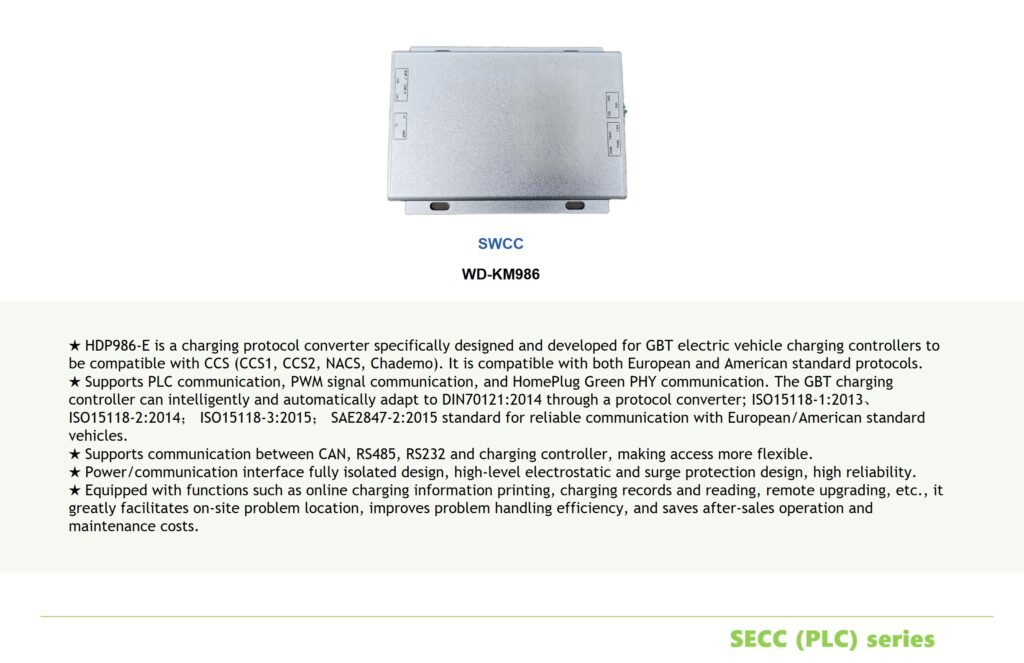
- Compatibility Adaptation: To meet the charging needs of vehicles from different brands, the communication circuit of the SECC must be compatible with multiple protocol versions. Adaptive switching between GB/T 27930-2015 and GB/T 27930-2020 can be realized through software configuration, avoiding charging failures caused by protocol differences.
Conclusion
The core technologies of new energy vehicle charging piles lie in the communication compatibility of SECC/EVCC protocols and the design of high-efficiency circuits. Through standard conversion and intelligent communication, the SECC protocol facilitates the globalization of Chinese charging equipment; while the EVCC protocol ensures charging safety with refined control and multiple protection mechanisms. With the popularization of 800V high-voltage platforms and ultra-fast charging technologies, charging systems will move toward higher power density and more intelligent collaborative control in the future.