
Drivers: More Than Just Discharging the Gate
The Division of Labor Logic Between UCC27524A and NCP81071B
“Do you think a driver is just a ‘switch’? In fact, it determines the system’s response speed, EMI level, and efficiency ceiling.”
In high-voltage, high-current applications like 20kW charging modules, whether MOSFETs/IGBTs are “well-driven” (i.e., operate optimally) hinges on the expertise behind the driver design. Starting with TI’s UCC27524A and ON Semiconductor’s NCP81071B, we can understand the differences in driving strategies between LLC and PFC circuits, as well as how “driver selection” becomes the key to gate protection, electromagnetic interference (EMI) control, and efficiency optimization.
🧩 I. Division of Labor for Driver Modules: LLC vs. PFC – Which Driver for Which?
| Driver Location | Driver Model | Package | Number of Channels | Driving Capability | Application Module |
|---|---|---|---|---|---|
| LLC Main Control | UCC27524A (TI) | SOIC-8 | Dual-channel | 5A / 5A | LLC Full-Bridge MOS Driver |
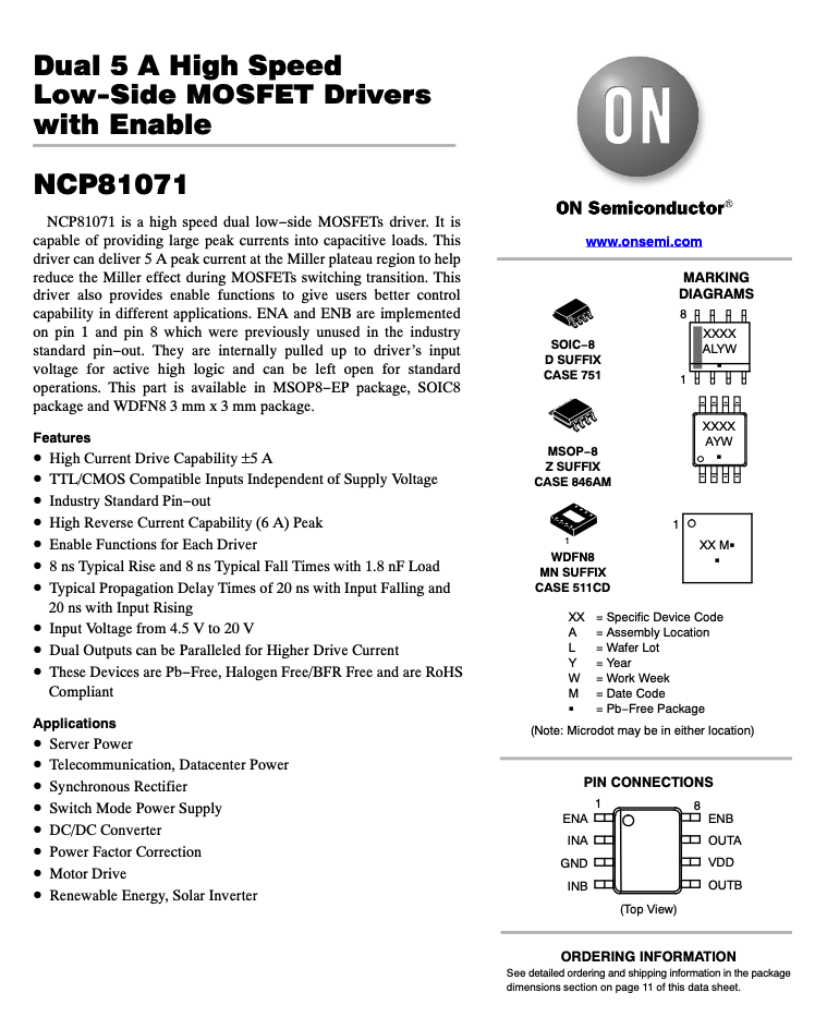
| PFC Main Control | NCP81071B (ON) | SOIC-8 | Single-channel | 5A | Low-Side Three-Phase PFC IGBT Driver |
- The UCC27524A is responsible for driving the high-frequency MOSFETs in the LLC section, with its two channels driving two pairs of bridge arms respectively;
- The NCP81071B serves as the low-side driver for PFC, controlling three sets of PFC switching tubes respectively.
🔍 II. Full Interpretation of the Circuit Path: PWM → Driver → Gate → MOS/IGBT
✅ Typical Structure of the Driving Link:
PWM Signal (MCU) → Driver (UCC27524A / NCP81071B) → Gate Current-Limiting Resistor → MOS/IGBT
- The driver amplifies the PWM signal and provides sufficient driving current to quickly charge and discharge the gate;
- It works with external gate resistors and clamping/TVS circuits to suppress oscillation and protect devices;
- PFC IGBTs require moderate switching speed to balance efficiency and EMI;
- LLC bridge MOSFETs require fast switching to reduce dead-time loss.
⚙️ III. Parameter Breakdown: Why This Matching?
🔹 Highlights of UCC27524A:
| Parameter | Value | Significance |
|---|---|---|
| Driving Current | 5A/5A (Source/Sink) | Meets requirements for fast turn-on and turn-off |
| Propagation Delay | 13ns | Extremely short response, suitable for high-frequency control |
| Input Negative Voltage Tolerance | -5V | Anti-interference design to improve system reliability |
| Turn-Off Characteristic | TTL/CMOS-Compliant Input | Can be directly controlled by MCU |
| Gate Negative Voltage Protection | Achievable via external diode | Realizes clamping protection |
🔹 Highlights of NCP81071B:
| Parameter | Value | Significance |
|---|---|---|
| Driving Capability | 5A (Sink/Source) | Compatible with IGBTs requiring large gate charge |
| Rise/Fall Time | 13ns / 10ns | Sensitive response with clean signal edges |
| Input Voltage Range | 4.5V–20V | Supports wide-voltage design |
| Quiescent Current | 180μA | Low-power design, contributing to system standby optimization |
🎯 IV. Driver Selection Logic: The Triangular Balance of Power, EMI, and Device Compatibility
In the PFC section, to reduce common-mode interference and IGBT tail current loss, the driver should not be excessively fast;
In the LLC section, where frequencies frequently reach 80–150kHz, the driver must “keep up” with the speed requirement.
In the LLC section, where frequencies frequently reach 80–150kHz, the driver must “keep up” with the speed requirement.
Key selection considerations include:
- Gate drive current (determines whether the switching device can achieve fast saturated turn-on)
- Drive symmetry (particularly critical for half-bridge arms)
- Propagation delay matching (affects synchronization and dead time)
- EMI and dv/dt suppression capability (whether it has soft drive control functionality)
🧪 V. Typical Circuit Design Recommendations: Protection First
- Gate Series Resistor
Limits current and suppresses oscillation; typically selected within the range of 1–10Ω, with the specific value determined by the type of MOSFET/IGBT. - Clamping Protection Circuit
Add a TVS (Transient Voltage Suppressor) diode or Zener diode to limit Vgs (gate-source voltage) within the absolute maximum rating (e.g., within ±20V) and protect the MOSFET. - Isolation of Drive Power Supply
Isolated power supply is recommended for high-side drives to avoid interference and common-mode current.
📦 VI. Conclusion: A Set of “Driving Strategies” Supports the Control Closed-Loop of High-Power Systems
In a high-power platform like the 20kW system, different drivers are not just passive “switches” that execute PWM signals;
they play a crucial role in ensuring energy efficiency, reliability, and protection mechanisms.
they play a crucial role in ensuring energy efficiency, reliability, and protection mechanisms.
- The UCC27524A emphasizes high speed, low latency, and symmetric control;
- The NCP81071B emphasizes compatibility with large gate charges and output anti-interference capabilities.
Together, they support the “neural center” of this system—behind every precise switching of MOSFETs/IGBTs lies the silent contribution of the drivers.